![]()
Established
in 1972


Products
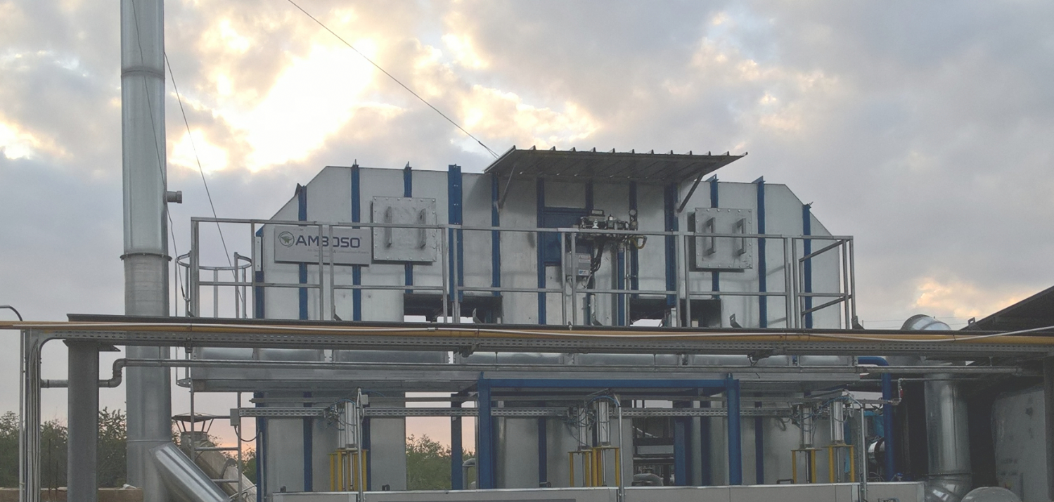
Regenerative thermal oxidizers

1. Type of technology
Thermal oxidation.
2. Contaminants which can be removed
All hydrocarbons.
3. Emission limits possible
Collection efficiencies exceeding 99% can be reached.
4. Description of the equipment and/or process
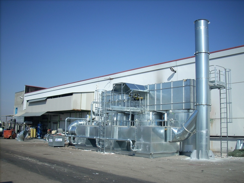
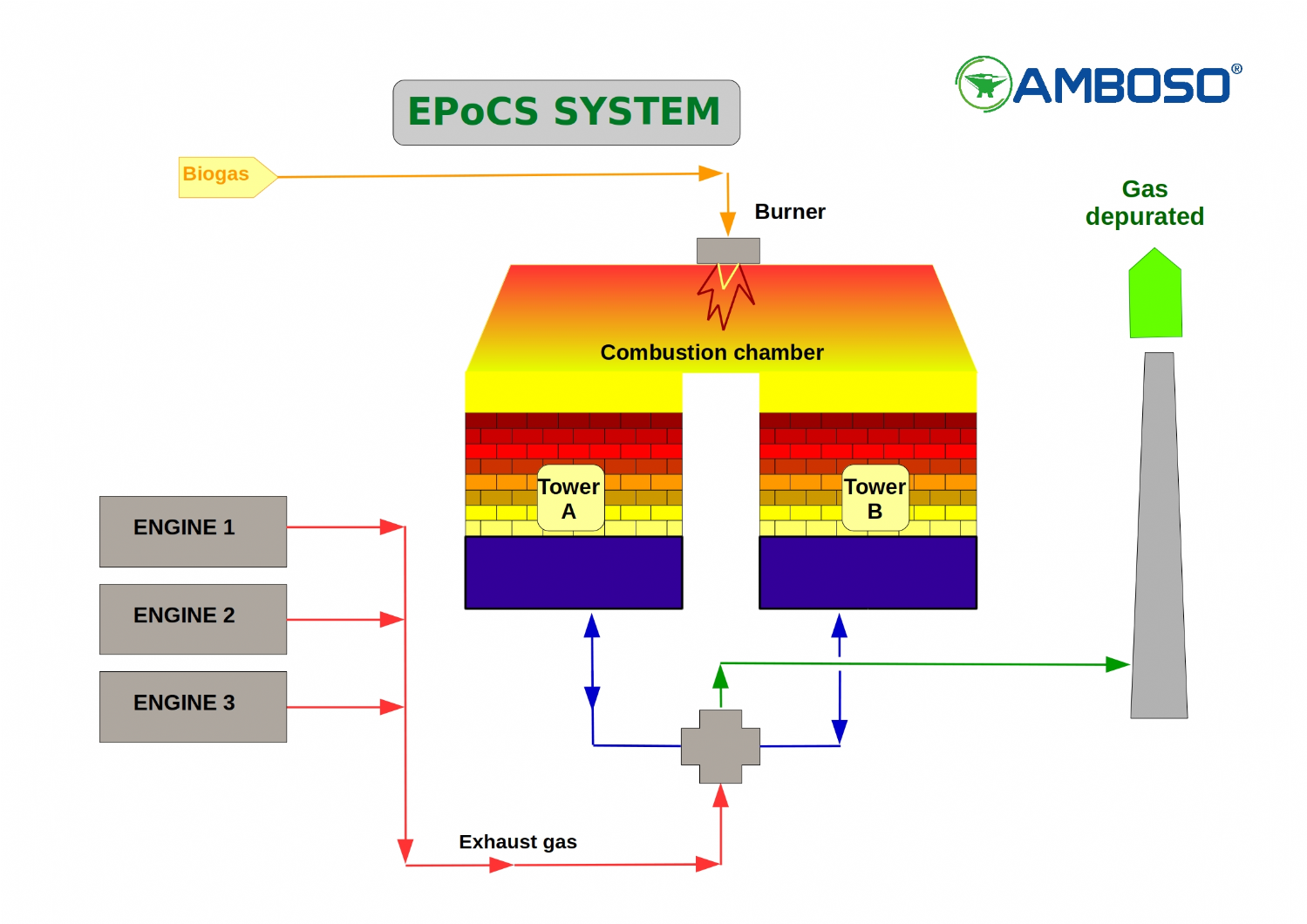
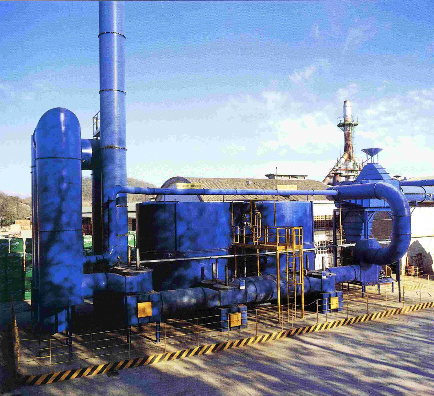
I.T.R. is the name chosen by Amboso for its new regenerative type of incinerator plant with intrinsic heat recovery, i.e. a combustion system in which the heat energy is recovered inside the plant with the maximum possible efficiency. Compared with other abatement systems, the regenerative combustion unit (incinerator) is ideal for the incineration of any type of volatile organic compound in gaseous form also in low concentrations (chlorinated and non-chlorinated solvents, inflammable compounds, hydrocarbons, odours); furthermore it has the advantage of minimizing running costs and consumption of primary energy sources.
The contaminants in the gaseous stream are eliminated by exposing them for a period of time in accordance with current regulations and at a temperature such that complete oxidation is always guaranteed. Likewise for this type of plant (exactly as for the catalytic incinerator) the combustion products formed by the exothermic reaction are mainly carbon dioxide and water vapour.
The thermal-regenerative combustion process is highly versatile as regards treatment of the gaseous emissions. Moreover it is practically unaffected by any variations in chemical composition of the emission, such circumstance frequently occurring in industrial processes involved with the manufacture of diversified products and which can vary rapidly over a period of time, depending on market requirements.
Energy consumption (high in conventional incinerator plants) is very limited for the regenerative combustion plant thanks to the heat recovery system which uses packing of ceramic material having the function of a “heat wheel” able to receive heat easily from such gas and store the heat, then give it back readily to the gas.
In short, the chief characteristics of these incinerators are:
Thermal-mechanical stability:
Appropriate choice of ceramic fibre, for internal lining of the combustion chambers, guarantees an optimum response of the system to heat stresses and therefore long-term perfect performance; the packing, consisting of small ceramic saddles is designed to withstand an unlimited number of cycles.
Flexibility - Versatility:
The preliminary heating of the system by means of a conventional burner, and the type of refractory lining allow the operating temperature to be reached quickly. So it is possible to disactivate the system with the necessary or Required frequency, thereby avoiding the stand-by phase; there is ample range for correct operation thanks to the reduced pressure drop of the ceramic beds as well as the flexibility of the flame type heat generator and availability of the geometric volume of the combustion chamber which ensures sufficient times of contact, of conservative value, between the process gas and oxidizing fluid.
Abatement or reduction efficiency:
The presence of a real combustion chamber ensures the full oxidation of contaminating substances;
while it also ensures: Reliability and easy operation, with minimum routine and unscheduled maintenance.
4.1 Description of the technical solution
Description of the principle of operation of the incinerator
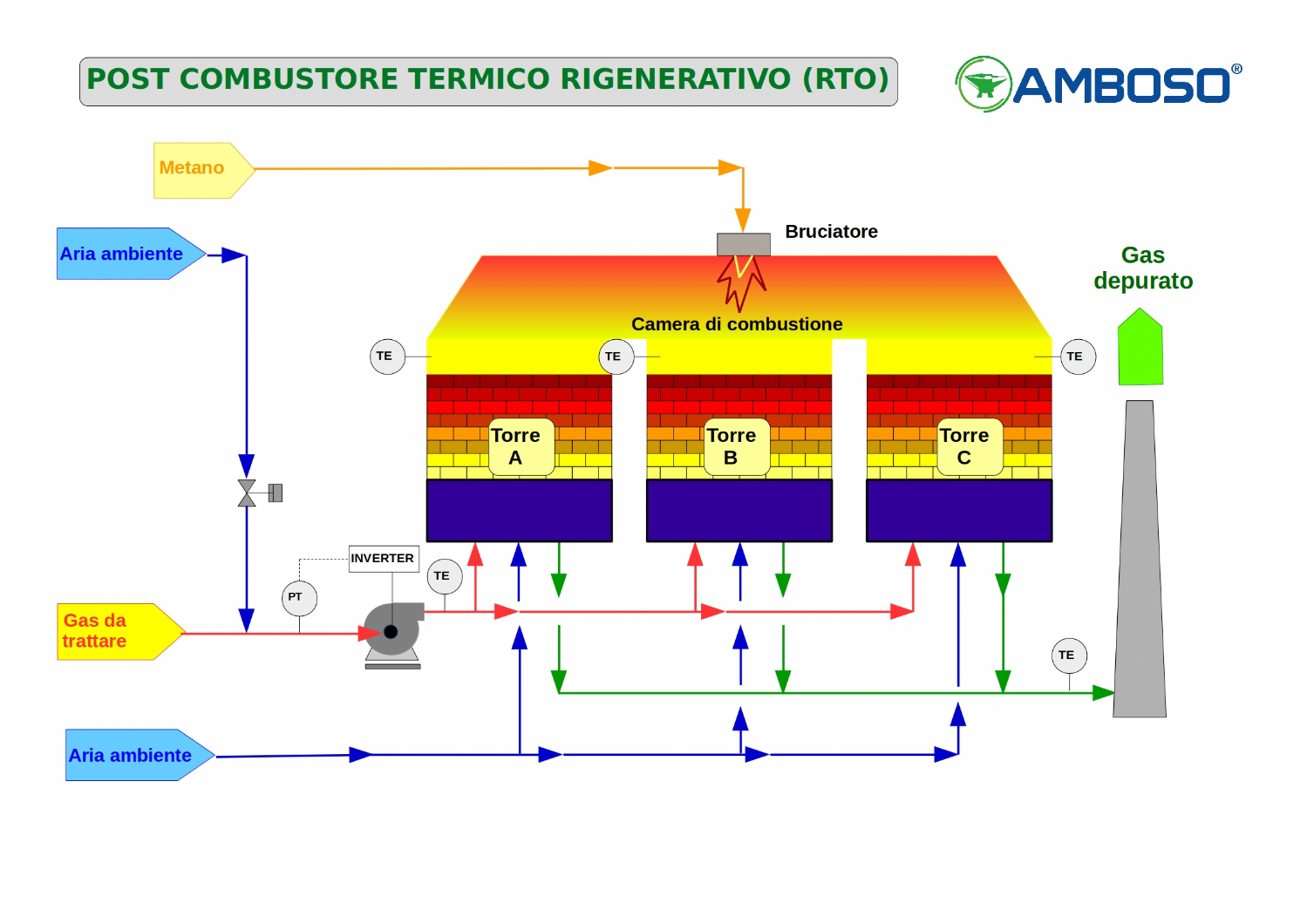
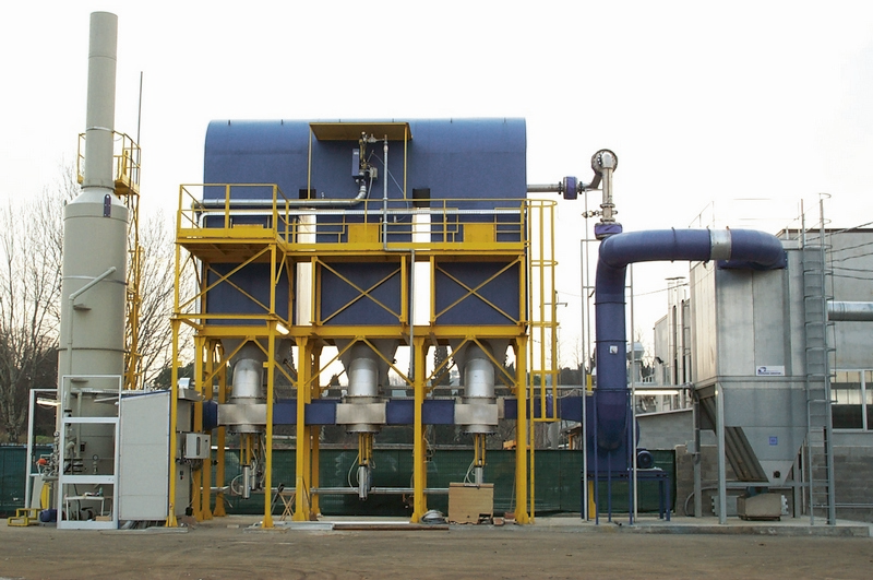
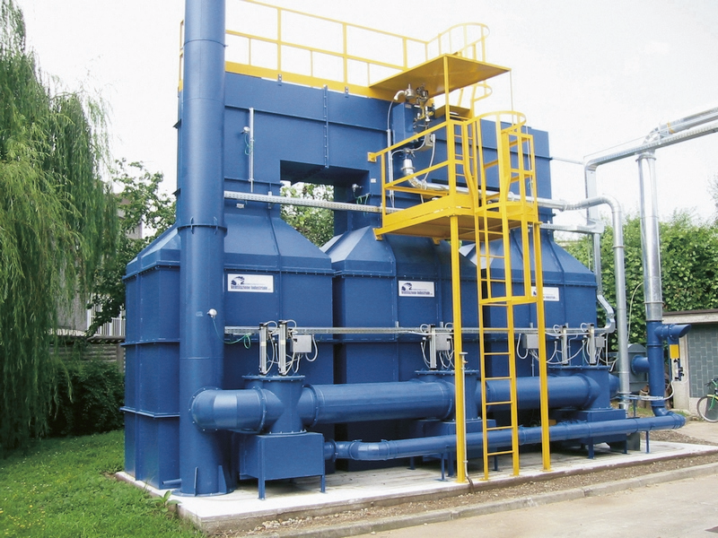
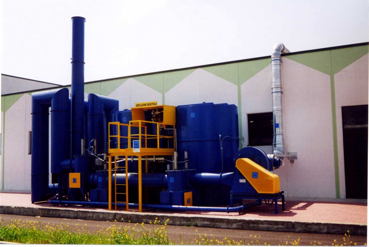
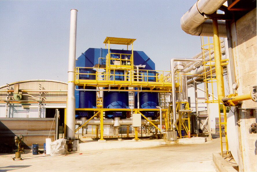
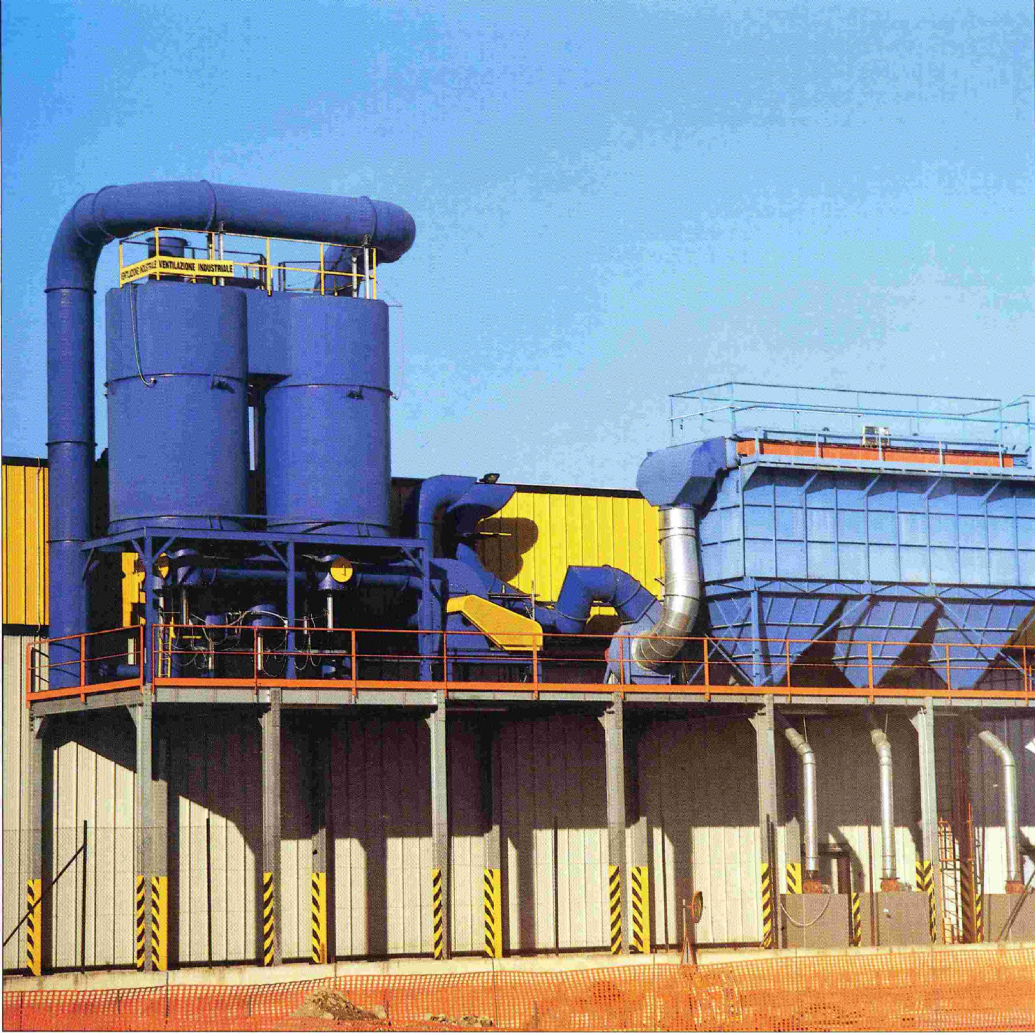
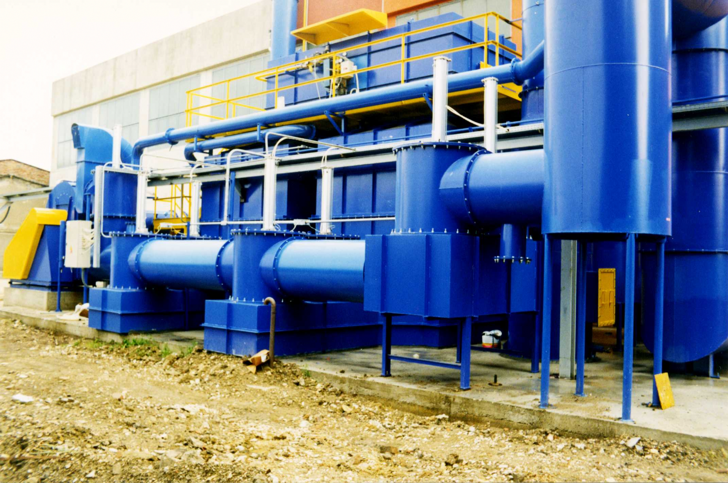
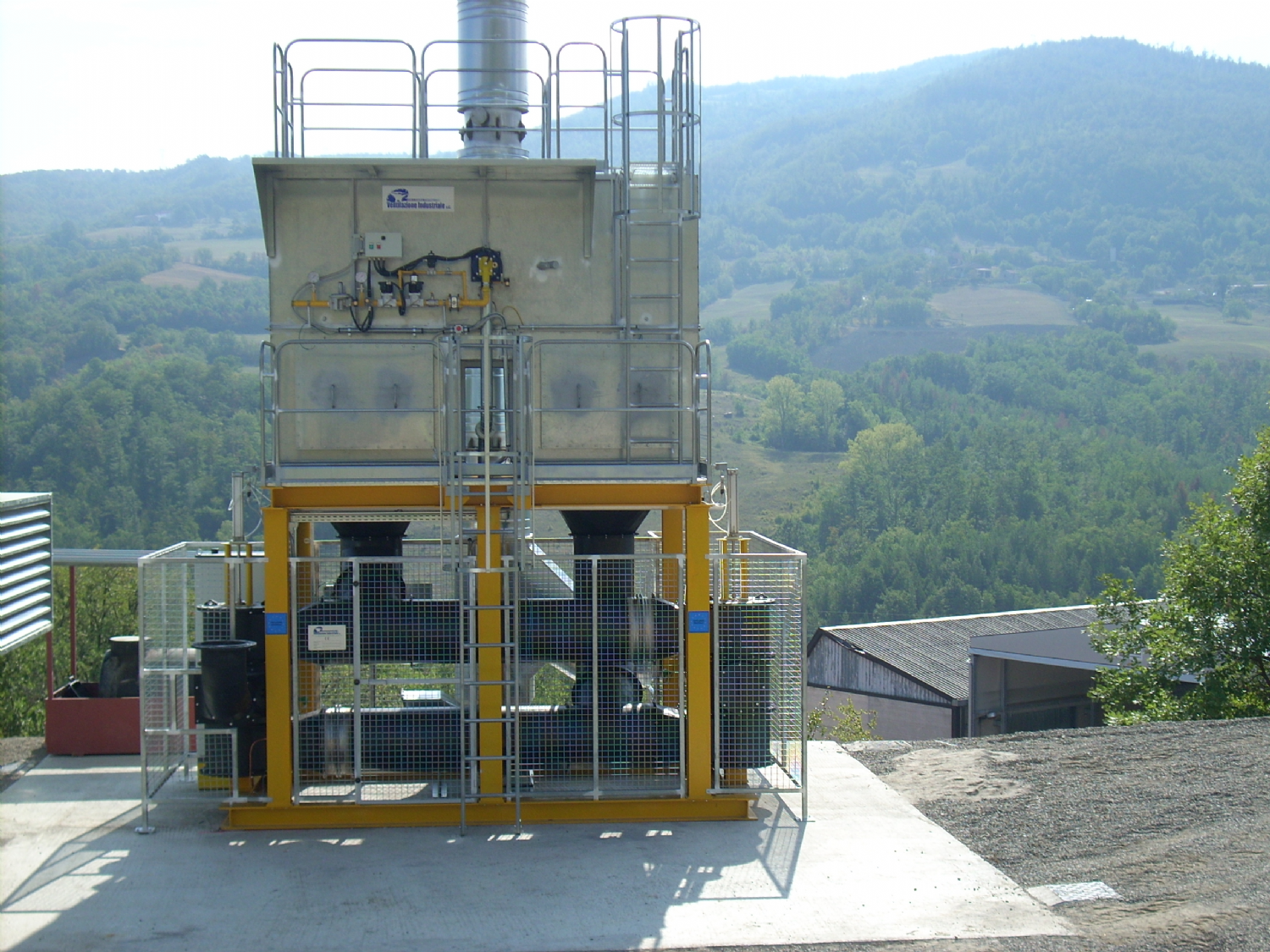
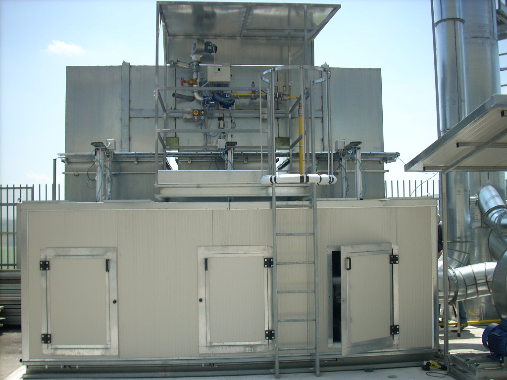
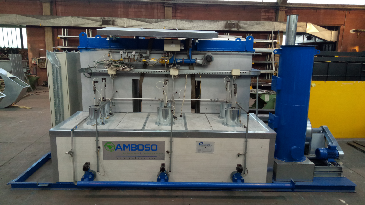
The gases extracted from production machines and/or their immediate surrounding environment are introduced in the treatment unit. This unit basically consists of three preheating/recovery regenerative chambers arranged vertically, and two horizontal combustion chambers, installed above the three regenerative chambers. The three chambers form part of a single body, of carbon steel sheet construction, internally lined with ceramic fibre 200 mm thick, in multi-layers and in modules, thus ensuring a temperature of the outer jacket less than 70°C.
The preheating/recovery chambers are packed inside with inert ceramic material which form three distinct masses of high thermal capacity. Such material is held by rugged grid of carbon steel plate construction.
The heat Required for plant start-up (i.e. preheating of the chambers and ceramic beds) is generated in the combustion chambers by means of an automatic burner of the proportional modulating type. The combustion unit (incinerator) can be by-passed by actuating a servo-controlled valve in semi-automatic or automatic mode.
Operation of the I.T.R. system is subdivided into the following phases:
A) Precleaning
B)Preliminary preheating with cold start
C)Flowing through preheated bed 1and recovery bed 2
D) Flowing through preheated bed 2and recovery bed 3
E) Flowing through preheated bed 3and recovery bed 1
F) Cyclic operation starting from phase c
Function of the precleaning phase is to ensure the complete elimination of any traces of combustible gas from the unit, before start-up, and is performed by causing clean air to flow through the cold plant.
During the preheating phase, two-speed fan VC1 is started at minimum flow rate (~1/3 of nominal capacity) and the auxiliary burner is activated. In such instant the cyclic operation of the incinerator has already started, even though the process gas has not yet been allowed to enter because the plant has still not reached the firing temperature. When such temperature is reached, the effluent can then start to flow into the system.
The dirty gas stream flows through the first bed of ceramic material and is heated until reaching a temperature close to self-combustion of the VOC molecules contained in the stream. Their thermal oxidation generates heat in the top part of the bed and in the combustion chamber, where such process is completed with the transformation of the contaminants into in CO2 and H2O. After leaving the combustion chamber, the carrier fluid mixed with the combustion products, meets and flows through the second bed, relatively cooler than the first bed, thus giving up most of its enthalpy to the ceramic saddles. The so-cooled gaseous mixture is then discharged via the stack.
After reaching the set temperature in the top part of the second bed, the system is switched to the cyclic operating conditions, i.e.: the gas flow is inverted so that first it enters the already heated second bed, then it passes into the third, cooler bed then enter the hoter third and the cooler first. This occurs at regular time intervals (60 to 90 seconds) so that all beds exchange function of preheating and recovery. In this way the unit makes alternative use of the heat built up in one of the three ceramic beds to heat the incoming gas while it builds up, in another bed, the heat of the outflowing gas. A series of automatic valves sends the gas stream to the various sections of the unit during the various phases of the operating cycle. Such valves, of the plate type and with pneumatic operator, ensure practically perfect gas-tightness.
The air stream always impinges two beds of ceramic material, while the third bed is on stand-by. During the regeneration cycle, the tower on stand-by is placed under negative pressure to draw in the dirty air which had not flowed through the combustion chamber during the previous cycle. This precaution allows achieving continuity in the results of VOC removal efficiency, also when changing the valves.
When a temperature measured in the central zone of the beds is found to be lower than the normal operating conditions, e.g. owing to low VOC concentration, auxiliary combustible gas is added to the feed gas by blowing it before the centrifugal exhaust fan, until the temperature in the beds reaches the maximum set-point. After reaching the temperature, the flow of auxiliary combustible gas is automatically shut-off by 2 solenoid valves installed in series.
The fan delivery line is of sufficient length to ensure good mixing of natural gas with the process gas prior to entering the combustion unit. A flow meter with function of low flow alarm is installed in such line as well as a measurer of the lower explosion limit with alarm function for high concentration of the combustible gas.
Abnormal conditions cause stopping of the flow of auxiliary combustible gas in the incinerator. Alternatively the heat Required for maintaining the Required temperature inside the beds, always if the heat supplied by the VOC is insufficient, is generated by means of the preheating burner installed in the combustion chamber. The two alternatives are chosen by an appropriate selector switch on the front panel of the control console.
A thermal resistor TE is installed downstream of the combustion unit on the stack. Purpose of this thermal resistor is to monitor continuously the temperature of the gases flowing out from the combustion unit. The alarm threshold signals the persistence of abnormal operating conditions in the incinerator and causes it to be stopped.
When the incinerator is stopped, fan VC1 is stopped while only the gas line from the recovery bed to the stack remains open. The incinerator (combustion unit) can be by-passed by opening/closing the process valves and opening the by-pass valve. A differential pressure indicator allows monitoring the pressure drops across the ceramic beds.
Amboso s.r.l. has supplied Fornaci di Manzano s.p.a. with a regenerative type of incinerator with reverse flow, for cleaning emission flows coming from brick kilns. The combustion plant allows incineration of the VOC present, by holding the combustion chamber temperature equal to or higher than 750°C, and contact times greater than one second. The Volatile Organic Compounds in the emission may be due to the additives added to the clay (polystyrene, paper mill sludge, etc.), Required for production of light-weight brick in paste form, with high sound insulation capacity, optimum thermal insulation and considerable thermal inertia. The high temperature of the emission fumes of the brick kilns can be exploited to obtain hot air T = 70°C ~ subsequently used in dryers in brick production, without causing a substantial increase in fuel consumption in order to hold the temperature in the combustion chamber.